Adjusting my setup is honestly my favorite part of each lab.
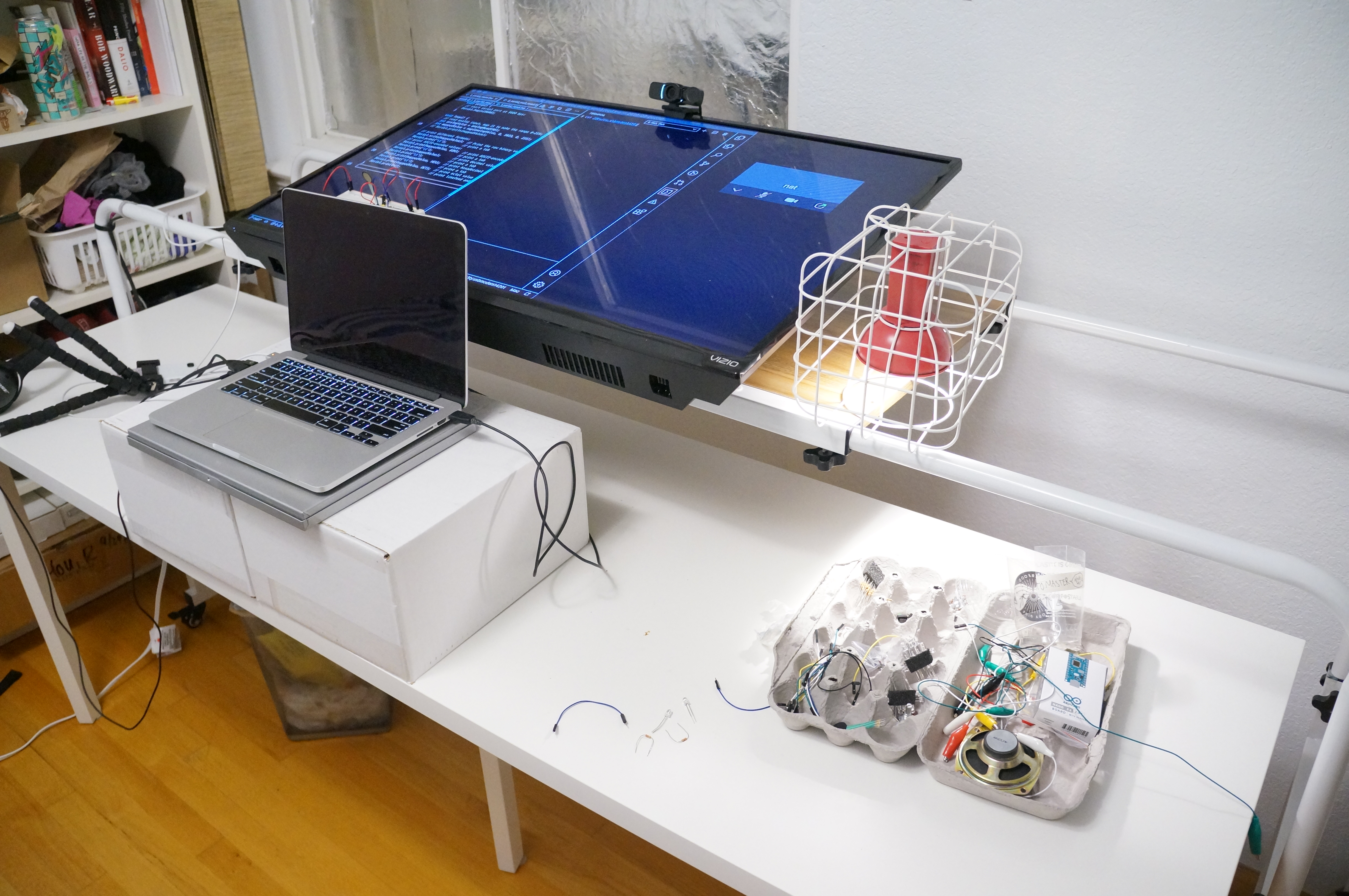
Classes are remote, and I got tired of sitting almost the entire day every day! This week, I adjusted my setup to make it just as comfortable to sit or stand.
Having the TV at that angle makes it easier to do work involving more precise control.
I also found some new tricks that allowed me to have a better documentation setup:
For documentation labs for this class, I typically need to record both the screen and the physical world simultaneously. I previously accomplished this by taking camera pictures of the circuit juxtaposed with a screen. The fidelity on these "screenshots" just isn't super great.
This week, I going to take screen recordings instead. I am now able to bring the real world into the screen using these two tricks:
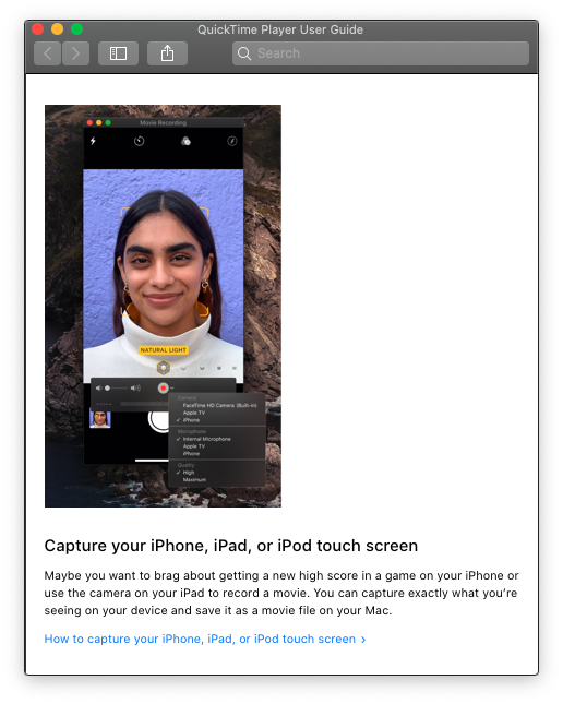
- When I was reading the help manual for QuickTime Player (reading documentation is, for some reason, something I do for fun), I found this cool feature:
You can view a iPhone's screen by connecting it to a Mac.
- I searched around for an iPhone app that displays just the camera, with no decorations around the image. I finally found one called Full Screen Camera -- it looks like the developer created it specifically for this purpose.
Putting all of this together, I could now capture both worlds in a single screen recording. Here's what the setup looks like:
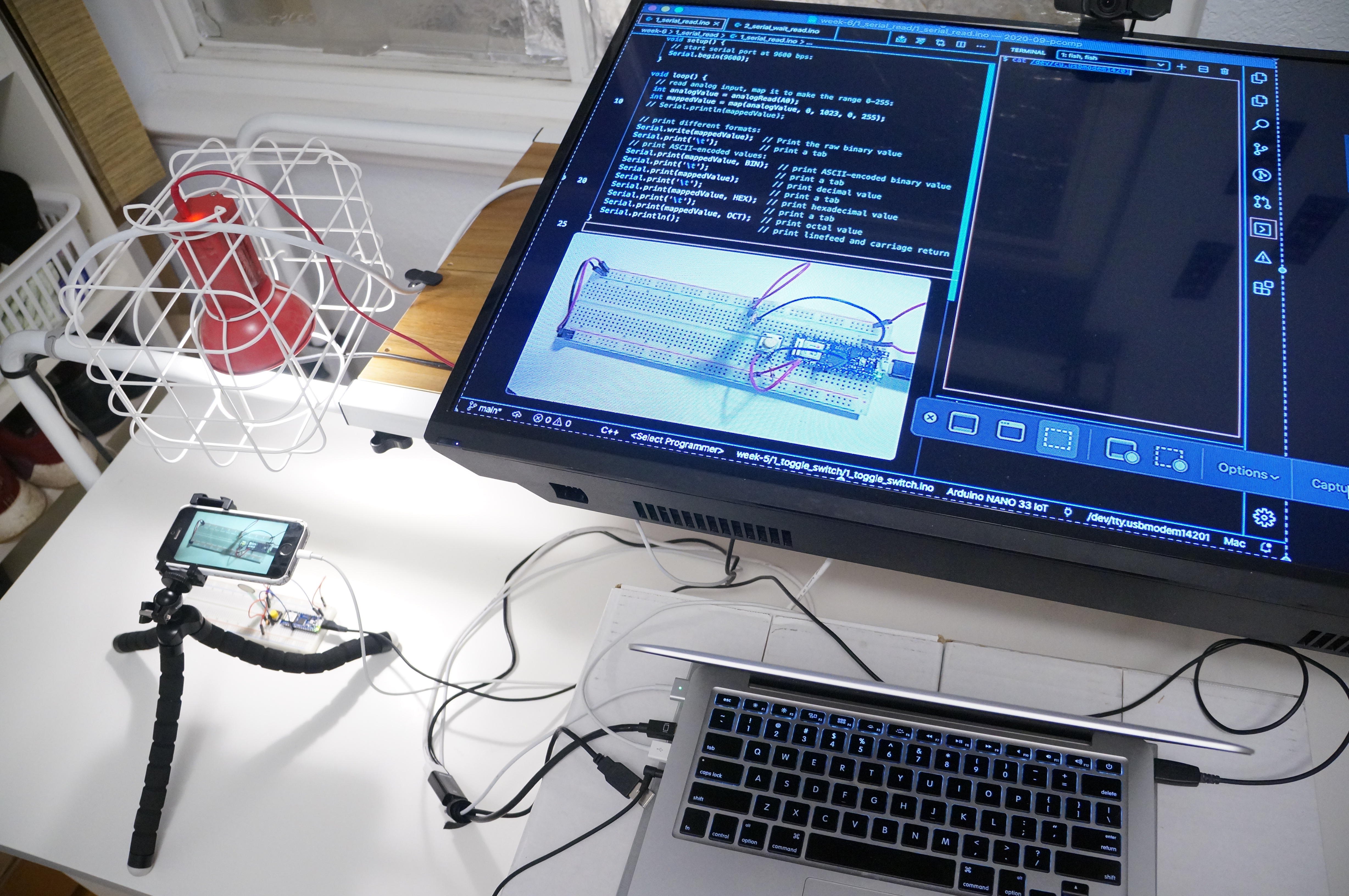
There is a slight lag with the phone screen mirroring, but I hope it's not too noticeable.
https://itp.nyu.edu/physcomp/lab-intro-to-serial-communications/
Using cat $PORT as a serial monitor. cat is
very robust and way less finicky than Arduino IDE serial monitor.
Unlike the previous program, this one prints out values only when a key is pressed.
💡 This took me way longer than expected to build. I managed to wire many wires incorrectly, including having an off-by-one error with the Arduino pinout, and forgetting to connect a wire for ground. It was not a fun process. :(
https://itp.nyu.edu/physcomp/labs/labs-serial-communication/lab-serial-input-to-the-p5-js-ide/
💡 I got very stuck doing this part. After about an hour of debugging,
I figured out that the issue turned out to be that I was using the
wrong port name. I was using
/dev/cu.usbmodem14201 (because the examples used
cu port names) but the correct port name is
/dev/tty.usbmodem14201.
The cat exercise above worked with the
cu port names! But here the cu port doesn't
work -- it doesn't cause serial.on('data') events to be
fired when data is written to the port for some reason.
Conflating this issue was another issue -- the serial connection often doesn't work unless programs are started in this order:
- Upload code to the Arduino.
- Restart the "p5.serialcontrol" app and open the port.
- Refresh the P5 sketch.
This is was first time using P5. I was impressed by how full-fledged the web editor is, and the fact that it was easy for the web app to connect to a physical device.
Same functionality as above, but here the devices are communicating using ASCII instead of binary.
https://itp.nyu.edu/physcomp/labs/labs-serial-communication/lab-serial-output-from-p5-js/
Having lived and learned through quite a few common mistakes earlier, I found this lab fairly straightforward. Here are the results.